Etching Circuit Boards Using Cupric Chloride and Acid Solution
The following information was extracted from portions of Chapter 6 in the book "Electronic Prototype Construction", authored by Stephen D. Kasten, Howard W. Sam & Co., Inc, 1983. The book is no longer in print. This information is presented on this web page with permission of the author, given to the web page owner, Rex. I have posted this information because of interest in this method after my posting about it in the newsgroup, rec.radio.amateur.homebrew in about 1997.
I (Rex) have finally gotten around trying these methods after meaning to for years. For me, the etching process was rather slow, but it did turn out fine.
My thanks to the author Stephen Kasten for allowing me to post this information.
Here is a portion of a note received from the author:
Rex - Thanks for your note ... regarding use and maintenance of the cupric chloride etching bath. It is still the bath that I use myself because it is so easy to regenerate and never has to be thrown out - it just keeps growing! Of all the information in the 1983 book, the section on cupric chloride etching generated the most interest from readers I have heard from.
P.S.: One new piece of information that I have found useful is that instead of using air bubbles to regenerate cupric chloride from the cuprous form, it is often easier to throw in some dilute hydrogen peroxide, which also results in no by-products.,
- Steve
From the book...
CUPRIC CHLORIDE ETCHANT · Cupric chloride solutions are very similar to ferric chloride as etchants, but the cupric system offers some distinct advantages in medium volume PCB prototype applications as follows:
- Simple regeneration of spent solution
- No waste disposal problems
- Lower cost
- Simple process control
- No sludging
At the same time, the desirable properties of ferric chloride are retained: high capacity for dissolved copper, and fast etch rates with suitable techniques, such as bubble, splash, or spray etching. One-ounce copper boards can be completely etched in less than one minute using cupric chloride at 49-54°C (120-130°F) in spray etching equipment. At these high temperatures the problems of HCl fumes and photo resist attack become more likely, but the metal chloride etchants can be used at room temperature as well if a fume hood or other exhaust system is not available; typical processing time for 1-ounce copper boards in a cupric chloride bubble etching tank at 25°C (77°F) is 20 minutes.
Formulation and Chemistry · The following formulation is recommended for a cupric chloride etching bath:
Cupric chloride, solid (CuCl2 · 2 H2O) 200 g
Hydrochloric acid, conc. (HCl, 37.5%) 100 g
Water, to make 1000 mL
Unless this bath becomes contaminated with undesirable materials (such as organic solvents, which can soften resist coatings), it will never require waste disposal. The reasons will be apparent later during the discussion of chemical control and regeneration.
Cupric chloride etches copper metal through the following chemical reaction:
CuCl2 + Cu -> Cu2Cl2
The initial solution color is a bright emerald green, and it turns to murky olive-brown as cuprous chloride is generated during etching. The cuprous chloride product is not as soluble as cupric chloride, so excess chloride ion is added to the bath to help complex and dissolve the cuprous form, preventing sludging. Sodium chloride (NaCl), ammonium chloride (NH4Cl), and hydrochloric acid (HCl) are commonly used as the complexing agents. HCl is recommended because it also serves to reverse the etching reaction through air oxidation:
2 Cu2Cl2 + 4 HCl + 02 -> 4 CuCl2 + 2 H2O
This air oxidation reaction is slow because oxygen is fairly insoluble in the etchant bath, but an air regeneration approach is ideally suited for bubble etching in a small laboratory operation. Since the bath is already equipped with an air inlet to generate bubbles, it is only necessary after etching to continue passing air through the solution until its color changes back to the characteristic bright green of cupric chloride.
Spray etching is a very effective commercial technique with cupric chloride because the etchant is partially rejuvenated when it mixes with air as a fine mist, activating the solution and decreasing etch time. It should be noted that in commercial high-volume applications regeneration of cupric chloride by air oxidation is too slow to be completely practical, so faster methods are used to reverse the reaction, such as direct chlorination, electrolytic action, or intense oxidation with hydrogen peroxide or sodium hypochlorite.
Air Bubble Etching · Etching with air bubbles is an ideal approach using cupric chloride, with the air providing several improvements over simple immersion in a bath. The action of swarms of tiny air bubbles surrounding a circuit board results in faster, even etching because agitation is increased, oxidation is enhanced, and the etchant is continuously converted back to its active chemical form. A practical air bubble tank can be easily constructed with the air source being a small laboratory pump, a large fish tank aerator, or even a vacuum cleaner with the hose reversed. A recommended approach is to generate an even flow of bubbles rising from the bottom of a tank, and to float the circuit board on top of the solution, allowing air bubbles to support and surround it. This approach is consistent with the general principle maintained throughout this book that prototype PCBs are most conveniently etched one side at a time. The mechanical action of air bubbles continuously rising to meet the copper surface is in effect very similar to spray etching, the optimum commercial approach.
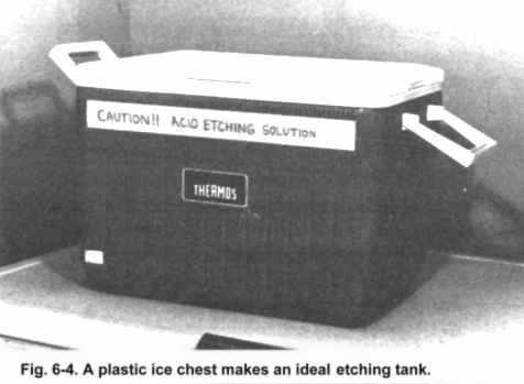
A practical cupric chloride etching tank can be made from a medium-size plastic ice chest, as shown in Fig. 6-4. The plastic material is compatible with the etchant solution, the container prevents evaporation, the drain plug is useful, and the lid can be lowered during etching to contain mist and acid fumes. If an immersion heater is added to bring the solution to 38°C (100 °F) for fast etching, the heater and thermostat must be constructed of chemically resistant material, such as quartz or titanium. Stainless steel does not stand up to cupric chloride. As shown in Fig. 6-4, the author's etching tank is used inside an old chest freezer that provides even greater containment for the corrosive etchant, and this allows the bath to be used in a workshop area without the benefit of a fume hood. The plastic walls of most freezers are acid resistant, and a large chest freezer makes an ideal sink for containing rinse trays, acid dip tanks, dirty gloves, and other potentially corrosive items.
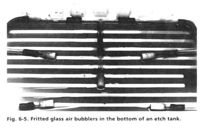
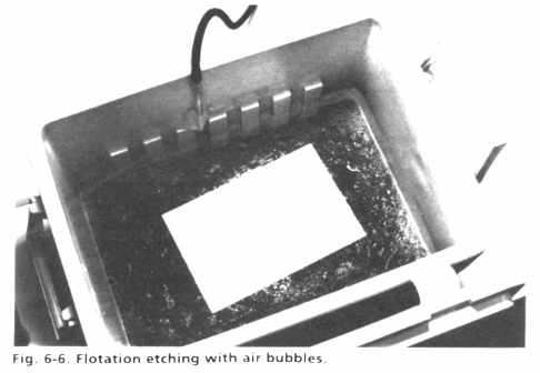
An internal view of the air bubble tank is shown in Fig. 6-5. In order to generate an even flow of small air bubbles, coarse fritted glass air bubblers (gas dispersion tubes) are spaced evenly on the bottom of the tank and connected with Tygon tubing and plastic "T" connectors. The tubing network is brought out of the tank in one spot as an air inlet, . where a low pressure (2-5 Ibs or 0.9-2.3 kg) air supply is connected during actual etching. The full tank is shown in operation in Fig. 6-6, illustrating the pattern of air bubbles swarming to the surface. Large circuit boards are easily floated in this tank, but smaller boards may tend to sink and must be supported on some plastic rails, or attached to larger pieces of scrap board. An inexpensive aeration system can be assembled from materials available at pet stores for use in fish tanks, such as sintered glass tubes and a small air compressor.
An alternate approach to generating air bubbles in an etching tank is to line the bottom with coils of plastic tubing connected to an air inlet, and punch tiny holes in the tubing with a miniature drill or with a red-hot needle. The overall objective is to get an even flow of small bubbles throughout the tank so that all areas of a floated circuit board will receive about the same etch action. Some laboratories use a deep, narrow tank instead of a wide, shallow container; in this case, the work is suspended vertically in the tank and air bubbles travel upwards across both faces of the board. Vertical air bubble etching tends to produce less even etching because the bubbles do not encounter the work uniformly. It is usually necessary to rotate circuit boards periodically on all four edges to produce evenly etched results in such a tank.
Cupric Chloride Bath Maintenance · The cupric chloride bath is initially prepared by mixing ingredients in the proportions previously given. The resulting solution has three important parameters that can be adjusted to maintain the bath at its optimum operating conditions: color, density, and HCl content. The proper control sequence consists of the following steps.
- Air-oxidize etchant to a bright green color
- Measure and adjust density to 1.17 g/mL
- Measure acid content by titration
- Adjust acid level with concentrated HCl
Color (Oxidation State) -- Bright emerald green is characteristic of acidic cupric chloride solutions. If any cuprous chloride is present, the color will become a darker olive-brown, but this copper form will always revert to its active cupric form with sufficient exposure to air bubbles under acidic conditions.
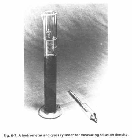
Density (Copper Content) -- The initial operating density (specific gravity) is 1.17 grams/mL. Density will gradually increase as copper dissolves into solution during etching, and as water evaporates. Etch rate will slow down and sludge may form with increasing density, so density must be monitored and periodically adjusted by adding water to the tank. A convenient device for measuring solution density is the hydrometer shown in Fig. 6-7. This device is available from scientific supply houses and operates on the same flotation principle used in common sulfuric acid battery fluid checkers. The hydrometer shown in the figure has a narrow, expanded density range from 1.15 to 1.25 g/mL, and is only 6 inches (152 mm) long; it can be floated in the etching bath, and the flotation level indicates density directly. If the bath is too shallow, a long narrow container must be used to hold a solution sample while the hydrometer is floated.
When density adjustments are made to cupric chloride etchant, the following equation can be used to add water back to the bath for dilution purposes, with the standard density objective being a specific gravity of 1.17 g/mL:
Y = X(dx - 1.17) / 0.17
where,
X is volume of present solution at (measured) density dx,
Y is volume of water to be added.
This dilution approach requires that the bath volume be easily measured, using level marks or a calibrated dip stick.
Acid Concentration (HCl Content) -- The initial hydrochloric acid concentration should be in the range of 3.5 to 4.0%, or 1.1 to 1.3 Molar. If the acid concentration gets much higher, problems such as resist degradation and excessive fuming will be observed. A lower acid level is not intolerable, but it will result in slower etch rates and a more difficult regeneration of cupric chloride from the cuprous form; sludging may also occur, because HCl helps dissolve etch by-products through complexation.
Therefore, an analytical method must be available to periodically monitor HCl concentration. The simplest approach is by titration, a technique easily accomplished manually with the aid of a few pieces of volumetric glassware. Note that acid concentration should not be measured before the etchant is completely converted to its oxidized bright green form through air bubble agitation, because acid is consumed in this regeneration process.
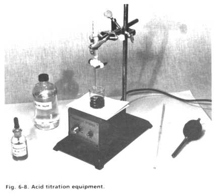
An acid-base titration requires that a measured amount of acid sample be mixed with a suitable indicator that changes color near the neutral pH region. A base solution of known composition is then slowly added to the acid with mixing until the indicator just changes color, showing that the acid has been neutralized. The initial acid concentration can be directly calculated from the volume of base consumed. Since our HCl analysis does not require extreme accuracy (+10% is fine), the titration procedure should not take more than 5-10 minutes and does not require extreme care. The following equipment and materials are necessary, and are pictured in Fig. 6-8:
- 1.0 mL pipet -- This calibrated glass tube has a mark to show when exactly 1.0 mL of liquid has been drawn in by suction.
- Rubber suction bulb -- Never use your mouth to fill a pipet with chemical solutions; the risk of pulling material into your mouth is not worth taking.
- 50 mL beaker.
- Magnetic stirring apparatus -- The solution can also be stirred manually during titration, but a laboratory stirrer using a magnetic bar provides a more convenient mixing system.
- 50 mL buret -- This is a long, thin, calibrated glass tube that is filled with base solution (titrant). The base is then dripped into the acid sample through a bottom stopcock, and the buret markings allow the volume of base consumed to be measured.
- Buret stand and clamp -- The buret must be clamped in a vertical position for accurate titrant delivery.
- Indicator solution -- Recommended indicator is 0.2% Bromphenol Blue in isopropyl alcohol; 3-4 drops are added to each 1 mL acid sample.
- Base titrant -- Sodium hydroxide, 0.10 Molar (0.4%). This standard titrant solution can be prepared by dissolving 4.0 g of solid sodium hydroxide pellets in one liter of water.
The titration procedure consists of the following steps:
- Measure out 1.0 mL of etchant solution with a pipet and drain it into a 50 mL beaker containing a small magnetic stirring bar. Dilute this sample with 20 mL of water.
- Fill a clean 50 mL buret with 0.1 Molar sodium hydroxide titrant and note the starting mark.
- Add 3-4 drops of indicator solution to the sample and place it on the magnetic stirrer base underneath the buret. The initial solution color should be yellow-green.
- Add titrant to the stirring solution while observing the color. Slow down this addition as the endpoint approaches, as evidenced by the formation of blue color in the region where the drops hit.
- Neutralization is complete when the solution becomes completely pale blue in color. Just one or two drops of titrant may be enough to cause the color to change at the endpoint.
- Note the amount of titrant consumed. The etchant is calculated to contain 0.31% HCl per mL of titrant consumed. Therefore, a fresh etchant solution containing 3.7% HCl would require 12.0 mL of titrant to reach the endpoint.
- As an example, assume that 8.0 mL of titrant was consumed for an unknown etchant sample. The acid concentration of the etchant would then be 8.0 x 0.31% = 2.5% HCl, which is low.
HCl Adjustment -- Acid adjustment should be made as the last step in process control, because the addition of concentrated HCl (37.5%) will not appreciably change the density of the etchant; concentrated HCl has a density of 1.19 g/mL, very close to that of etchant. The actual adjustment is made as follows. Assume that the acid concentration is a low 2.5% from the titration test. We have three gallons of etchant in the tank and want to bring the acid level up to 3.7% HCl. The necessary amount of concentrated (37.5%) HCl to be added is calculated from the following equation:
Y = X(3.7-A) / (37.5 - 3.7)
where,
X is initial etchant volume,
A is initial etchant HCl concentration in %,
Y is volume of 37.5% HCl to be added.
For the 3 gallon @ 2.5% example, the amount of acid to be added would be:
3(3.7-2.5) / (37.5-3.7) = 0.1 gallon, or 450 mL
Wear rubber gloves and safety glasses, and be extremely careful when handling concentrated acid. Never pour any material directly into concentrated acid, which can cause splattering; always add the acid to the other material. A well-ventilated area is necessary to avoid acid fumes, which are both a corrosion and a breathing hazard.
Etchant Disposal · The interesting characteristics of cupric chloride etchant result in the fact that the bath will never contain materials other than cupric chloride, HCl, and water following air oxidation; this statement assumes that no significant contamination occurs, and no metals other than copper are etched. Therefore, waste etchant is never generated. The solution volume will gradually grow as periodic water and acid adjustments are made to counter the increasing copper content, a result of etching circuit boards. Excess etchant can be sold or donated to other persons interested in printed circuit board fabrication. If the bath becomes contaminated with undesirable materials (such as organic solvents) it must be disposed of using the same precautions as with ferric chloride. Neutralization and mixing with concrete or mortar mix is the safest way to render a chemical etchant immobile for landfill.
*** The following section is repeated from an earlier section of the book which covered using FeCl as an etchant. This is repeated here for those who prefer to used FeCl, and also because this section gives a bit more detail on the subject. ***
Etchant Disposal · Spent ferric chloride etchant is not easily regenerated chemically because of the buildup of sludge, and because the copper and iron ions are difficult to separate. However, disposal is a difficult problem and accounts for the growing unpopularity of this solution in industrial applications. Metal drain systems will be quickly attacked by FeCl and its fumes, the copper content will create environmental problems and sewer lines may become clogged with sludge when ferric chloride combines with alkaline materials, such as caustic drain cleaner. These problems explain why ferric chloride etchant is only recommended for occasional use. On a small scale, exhausted etchant may be properly disposed of by neutralizing with caustic or sodium carbonate, and mixing with a suitable amount of concrete or mortar mix. After the mass hardens, it can be safely thrown in a landfill dump with the etchant converted to an immobile form.
Post-Cleaning · As with ferric chloride, cupric chloride will leave undesirable deposits on circuit board surfaces following etching. The most common residue is cuprous hydroxide, which is water-insoluble and appears as a yellow film on laminate surfaces. Cuprous chloride can also appear as a white residue if the etchant is low in acid content. Both of these contaminants are efficiently removed by soaking the board in 5% HCl following etching and resist stripping, and then rinsing well under running water.
ETCHING PROBLEMS · Various etching problems have been noted throughout the chapter, but the most common problems will be summarized in this section, together with possible causes and solutions. It will be assumed that KPR 3 photo resist is used for image transfer, and that cupric chloride solution is used for bubble etching.
Resist · Resist peels, degrades, or otherwise breaks Bown during etching -- this is usually due to improper copper surface cleaning prior to photo resist coating, resulting in poor adhesion of the resist. Poor adhesion can also be due to lack of a post-bake step for the final resist coating. Some other possible causes for resist degradation are too thin of a coating, etchant temperature too high, acid concentration too high, excessively long etch times, and the presence of solvent in the etching tank.
Long Etch Times · Exhaustion of the bath is the most likely reason for long etch times, requiring chemical rejuvenation or etchant replacement. If etchant becomes too concentrated due to water evaporation, etch time will also increase; a density measurement will reveal this condition. Low HCl acid concentration is another process control situation that results in long etch times. Assuming that the bath chemistry is properly balanced, etching time can usually be shortened by increasing agitation and by raising the operating temperature of the bath.
Uneven Etching · Uneven etching is illustrated in Fig. 6-9 with a partially etched board that has some areas completely resolved, while other areas (light-colored) contain substantial amounts of copper yet to be removed. Uniform agitation will prevent uneven etching, and this is the reason why an even pattern of air bubbles should be generated in the bubble etching tank. If certain areas of the bath are observed to produce consistently faster etch action than others, it may still be possible to obtain overall even results by moving the board around in the solution every few minutes.
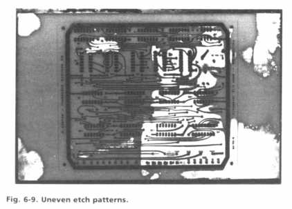
The situation shown in Fig. 6-9 is undesirable because it requires that some areas of the board be exposed to etchant longer than necessary, causing pattern undercut and resist degradation. Unevenness in etching will always occur to some extent. For example, board edges and areas with many closely spaced traces will generally etch faster than open copper areas. However, as a general rule, once etchant breaks through to the PCB laminate in one spot, the rest of the board should be completely etched within an equal additional time period.
Etchant Does Not Attack Copper · Etchant does not attack copper in some areas where it should -- the culprit is usually a thin film of photo resist or dye scum remaining after image development. Rubbing the board with a soft cloth soaked in isopropyl alcohol may remove the offending film, but this may not help if the pattern has been well-baked. In such a case, it will be necessary to remove the board from the etching bath, wash and dry it, and scrape off the undesirable scum using a razor knife or other sharp metal object. Very thin films of photo resist may not be noticed after dyeing the resist pattern, because this coating is not thick enough to retain dye. Therefore, it is good practice to stop and examine all circuit boards after the first minute of etching; copper areas that are properly attacked will change from shiny bright to dull reddish-brown in appearance.
Excessive Undercut · Pattern undercut occurs due to lateral etch action instead of the desired perpendicular attack. Long etch times in an exhausted bath tend to promote this problem. Undercut is minimized by fast etching and good solution agitation at the surface of the board. Spray etching is the optimum method to avoid undercut because it produces perpendicular etch action and fast results. Bubble etching is also a significant improvement over simple immersion in a solution, which can produce almost as much lateral as perpendicular attack.
Sludging in the Etch Tank · Sludging in the etch tank should not ordinarily occur with cupric chloride solutions containing excess chloride ion in the form of HCl. Some users add 10% sodium chloride or ammonium chloride to help complex and dissolve cuprous chloride solids. Sludge will precipitate if the bath density becomes too high, however; the presence of solids interferes with etch action and leaves residue on the surfaces of the finished board.
Corrosion of Circuit Board Traces · Extensive copper corrosion is almost always a result of poor surface cleaning following PCB etching. Etch undercut promotes trace corrosion because it produces nooks and crannies which retain etchant residues. To prevent this problem (which shows up as discoloration at the edges of metal traces) use HCl at 5% concentration with steel wool scrubbing. When acid is used for cleaning, it must also be completely removed with a good water wash, because mineral acid will attack solder joints. Even properly cleaned copper circuit traces will eventually discolor through air oxidation, making the metal surfaces difficult to solder. This is the main reason that a final solder coating should always be applied to copper PCBs, as detailed in Chapter 7.