Adapting a new LCD for GR-135
The Problem
Recently (Spring 2016) there were a number of used radiation meters sold on eBay. They are SAIC Exploranium GR-135 detectors. They were probably originally sold in the mid-2000's. Unfortunately, many of them had failing LCD displays with lots of dead vertical pixel columns. With so many having failing displays within about 10 years, there must have been a design failure in the LCD modules that were used. The following picture shows the problem on one meter.
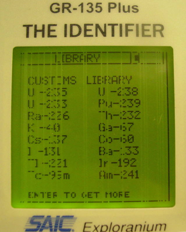
Display with dead pixel columns |
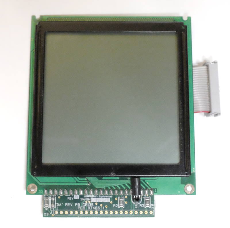
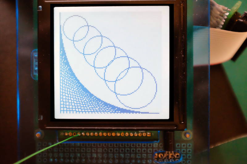
Initially I had hoped that something in the LCD module could be fixed. The GR-135 unit was taken apart and the LCD module removed. I found an Arduino library and was able to write a test program to exercise the LCD module. The following picture shows this program displayed on the LCD. In this picture, I had already removed the metal bezel that was around the glass portion of the LCD. The many dead vertical columns can be seen in the picture.
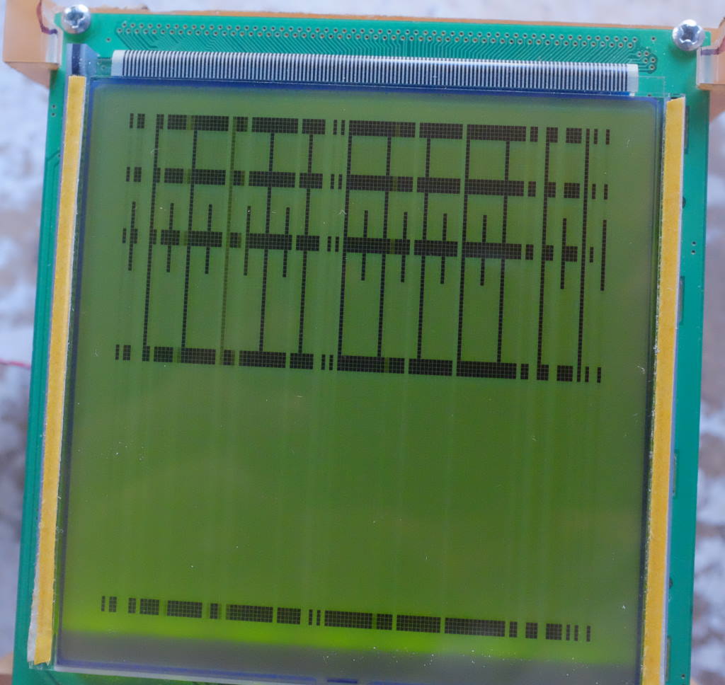
Test image. The four thick horizontal lines should be solid across the whole display. The many dead vertical columns can be seen. |
The LCD has a pixel size of 128 x 128. At the top of the glass of the LCD there is a short S-shaped cable that connects to the circuit board of the module. It is normally hidden within the metal bezel that has been removed. This cable has visible traces that are black. I carefully counted them and got 128 across the cable, so I think each line probably drives one column of the display. The following picture shows a closer view of this cable.
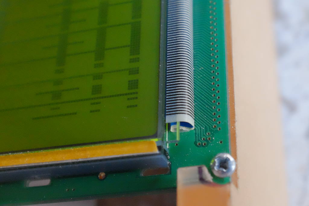
Flex cable connecting the LCD glass to the module's circuit board. |
While the test pattern was running, I pressed down on the cable, where it joins to the glass, in the vicinity of dead columns. I was able to see some changes in one or two columns but nothing that looked like a repeatable improvement. From this, I assumed it was unlikely that the LCD module could be repaired. Fixing the problem would require finding an equivalent module to replace the bad one.
The original LCD module
The LCD module used in the GR-135 was a Kingtronics 128128A. A replacement must have the following characteristics:
- Graphic display with 128 x 128 pixels
- Based on a T6963 controller chip or equivalent
- Has a 5 V backlight
- Fits in the available space in the GR-135
Through the Yahoo Gamma Spectrometry group, I connected with Tom King who had also purchased one of these GR-135's with a bad LCD module. We both began searching for a replacement LCD module and sharing our results. Pretty quickly, we both found a short datasheet that seemed to exactly match the module we needed. The following pdf file is that document.
From this, I have extracted the dimensions for the proper module (in mm). In that drawing, I have circled the three critical dimensions for fitting in the available space of the GR-135.
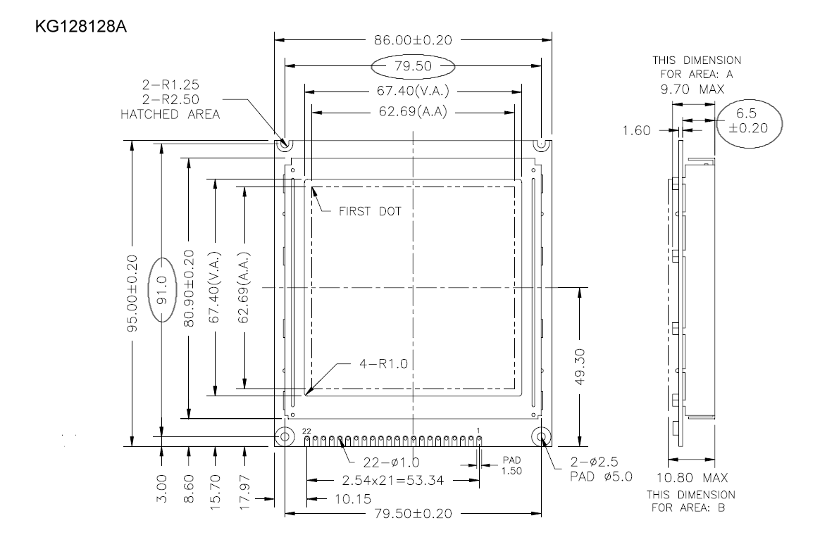
Dimensions for the proper KG128128A LCD module. Three critical ones are circled. |
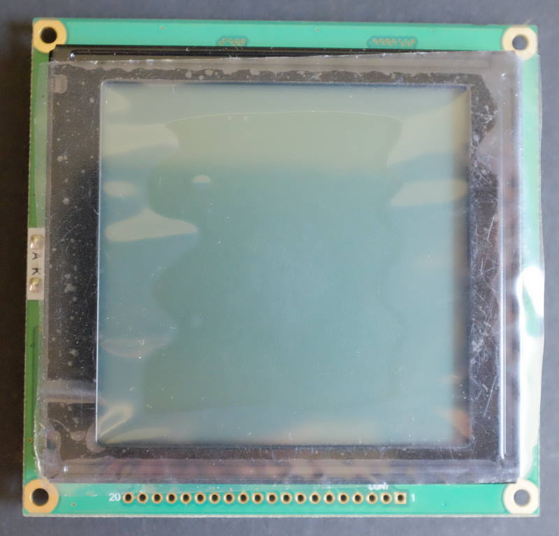
Here are front and back views of the original LCD module. It connects to the main GR-135 unit with a 20-pin (2 x 10) connector. The connection pins on the LCD module are a single row of 22 via pads. The connection translation is managed by the small interface card at the bottom of the module. Mainly, this interface card just routes the proper signal lines. It also has two resistors that pull up two signal lines to 5 V, and one resistor that is in series with the backlight voltage. The final function is to mount a DS1821 temperature sensor and provide it 5 V power. The temperature sensor device is also obsolete, so hard to obtain now, but the original should still be good. The output of the temperature sensor is used to adjust the contrast voltage to the LCD and probably to calibrate the output of the NaI radiation sensor.
Original LCD module front. |
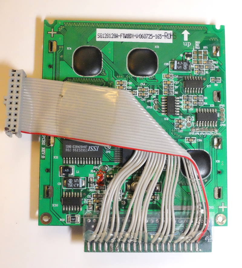
Original LCD module back. |
I worked out the connections on the small interface card and they are described in the tables of the following pdf file document.
It seems to be very difficult, at this time, to find LCD modules that are available in small quantities and also are dimensionally and electrically equivalent to the module shown above. Tom recently got one from a Chinese vendor that seems exactly right except that the display is white on blue. I haven't heard any more details on availability of this version, so I will only discuss, on this page, another option I found.
Crystalfontz LCD's
Searching for LCD modules, I found a vendor in Washington state, Crystalfontz, that sells a large variety of new LCD modules. On their site I first set results to 128x128 graphics displays and then looked for those with the necessary T6963-compatible controller. From this list I found two candidates. Eventually I ordered one of each to try for compatibility with the GR-135.
The most similar module seemed to be the CFAG128128A-YYH-TZ module. This has a display color style that seems the same as the original and a display area that is about identical to the original. Unfortunately, it had two issues. The size of the circuit card was a bit larger than the original and the thickness of the module was greater than the original. I thought these would be problems, and when I got the module, I can't see any way to fit it in the available space in the GR-135.
The following two pictures attempt to show the tight tolerances that make it difficult to accept an LCD module that is bigger than the original. The first picture shows the front feet on the main GR-135 circuit module that attach it to the top cover. Two screws pass upward through the two holes to fasten the feet to the cover which would be on top of the unit shown. The top edge of the circuit board of the LCD module rests right against the inside edge of these feet. Two more screws attach the circuit board to the top cover. The slight round cutouts seen in the feet in the picture are to accommodate the heads of these screws. The second picture shows the same feet from the side. The drawn lines represent where the top cover attaches. The LCD card would be below the drawn lines and extend to the left in the picture. If the bezel of the LCD is thicker than the original it forces the board down in this picture, which is limited by the sloping base of the main feet.

Main GR-135 module, mounting feet to top cover. |
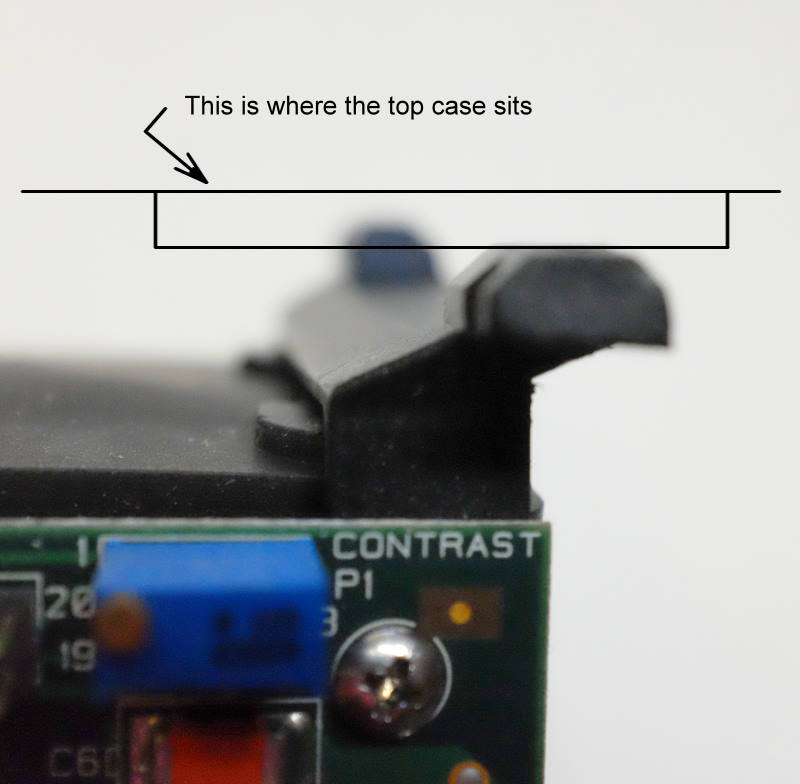
Feet from side. Lines represent top cover. |
This slightly larger CFAG128128A-YYH-TZ module looks to be impossible to fit in the available space.
Crystalfontz CFAG128128I-TFH-VZ LCD
The other module I ordered is a Crystalfontz CFAG128128I-TFH-VZ . This module is smaller than the original which, unfortunately, means the display area is smaller than the window in the GR-135 case, so it is a little harder to see the details. The smaller size does mean it can fit in the available space in the GR-135. This module is thin enough that is fits easily in the space between the cover and the main module. This version also has a different color display. It is black letters on a gray background or white background with the backlight. This may be better contrast than the original.
I was able to adapt this LCD module into the GR-135 but there were two major items that needed to be constructed to use it.
- A bracket is needed to allow the small module to mount onto the original mounting holes in the top cover.
- The original electrical interface adapter card can't be used because the module's connector holes are on a closer 2 mm spacing and also because the signals are in a different order than on the original module.
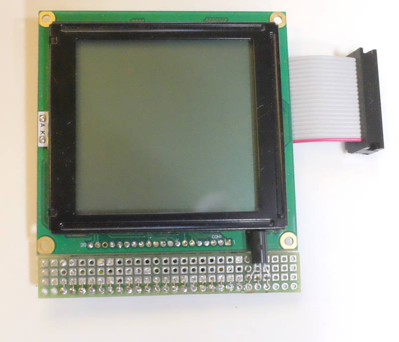
The next two pictures show the front and back of this new, smaller CFAG128128I-TFH-VZ LCD module. The display area on the original module was about 2.7 inch (7 cm) square. This smaller one is about 1.9 inch (5 cm) square.
New LCD front. |
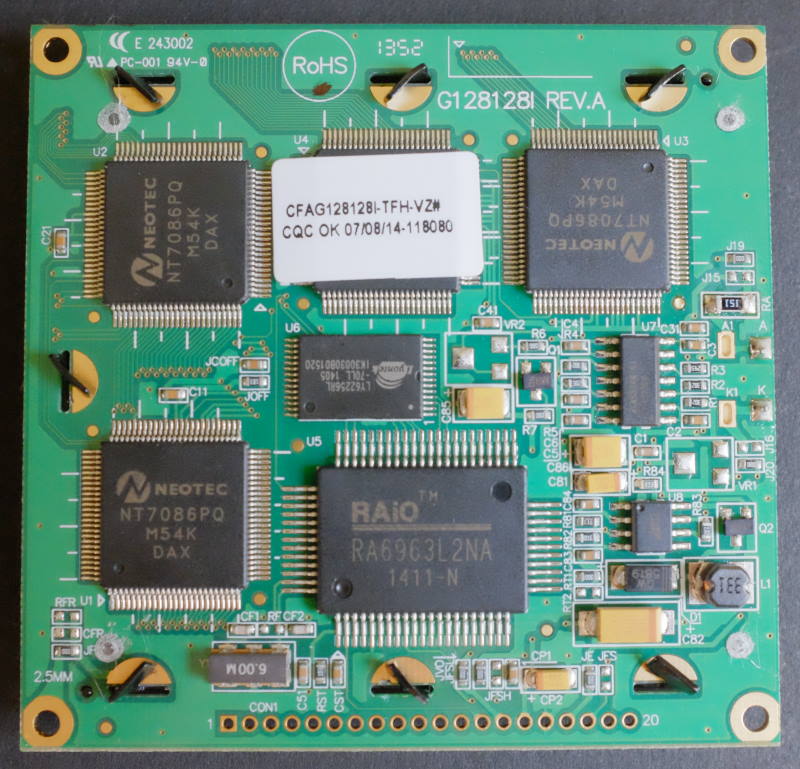
New LCD back. |
Mounting bracket
I made the new LCD mounting bracket from ~ 0.110 inch thick acrylic sheet. There is a square hole through the center to allow the bezel of the LCD module to pass through. One end of the hole is expanded to give clearance for the connector pins of LCD module. A slot is also cut to give clearance for the DS1821 temperature sensor. There is also a clearance cutout on one side of the center cutout to give room for the backlight connections of the module. I cut this 0.030" deep but it could have been cut all the way through. Four holes are drilled to allow mounting the module to the bracket. These 4 holes are threaded at 2-56 to accept 4 screws I provided to mount the LCD. An additional four holes are provided to accept the original screws that mount the bracket where the original LCD was mounted. The top two of these holes are in slight protrusions that fit into the indentations in the front feet of the main GR-135 module. The mechanical interface on this end of the bracket is very tight. The following diagram and picture show the shape and overall size of this bracket.
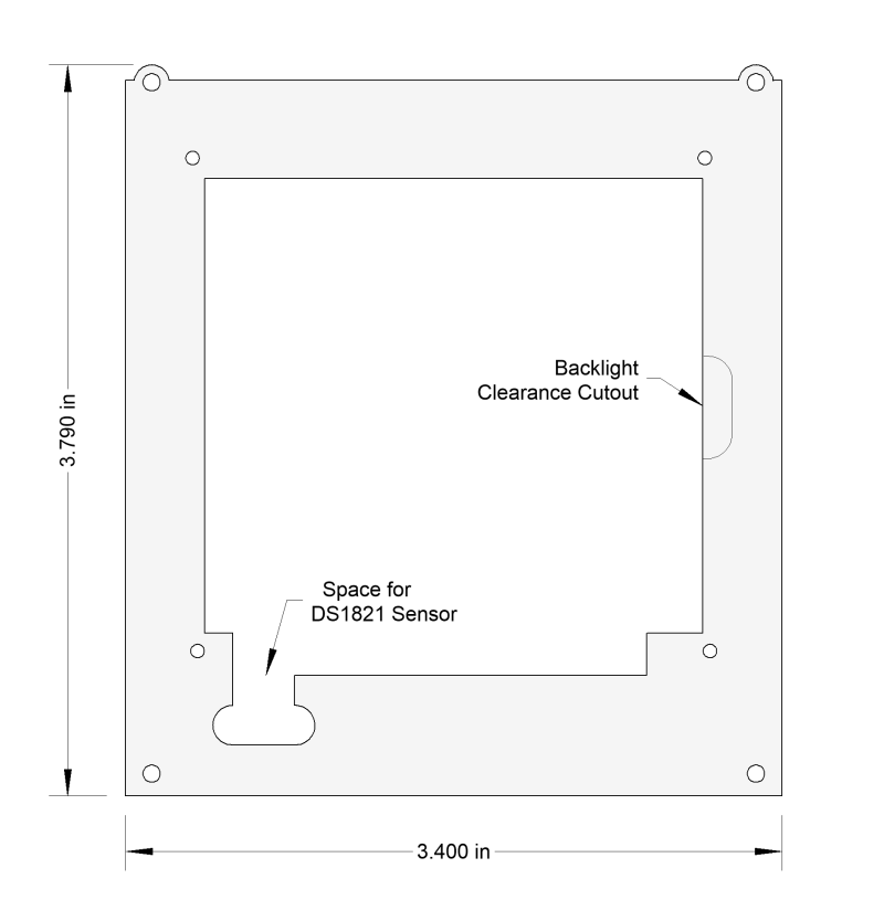
LCD bracket diagram. |
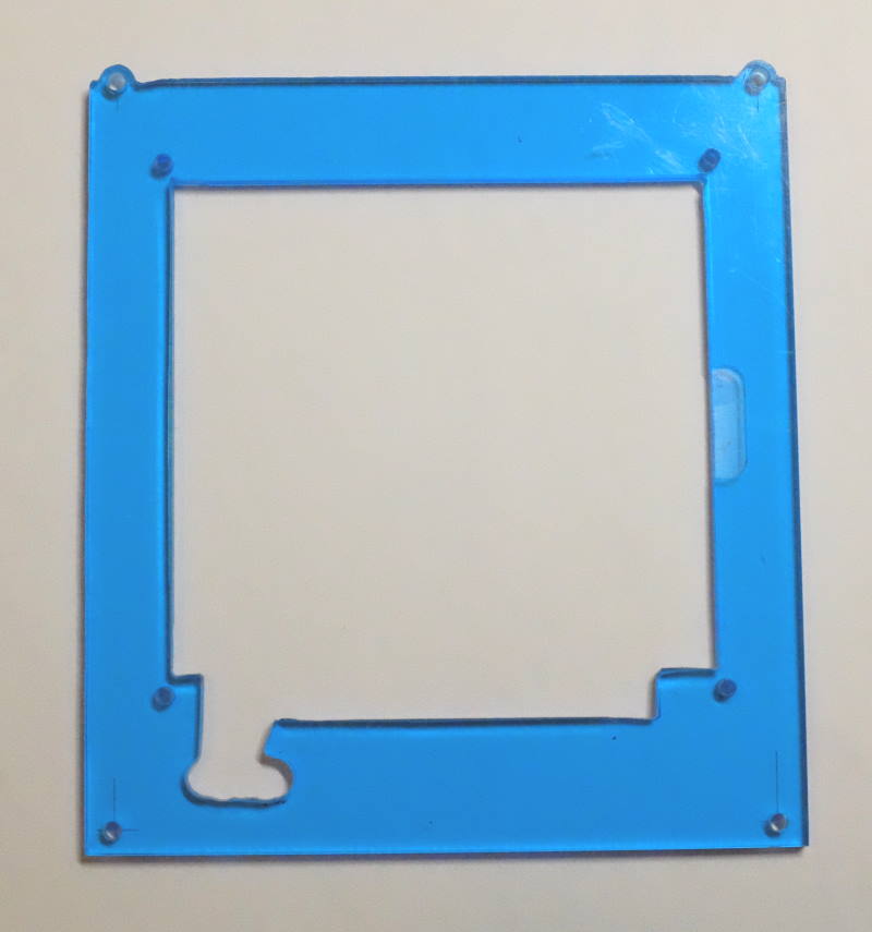
Actual LCD bracket picture. |
A detailed drawing of the bracket with accurate dimensions is provided in the following pdf file document.
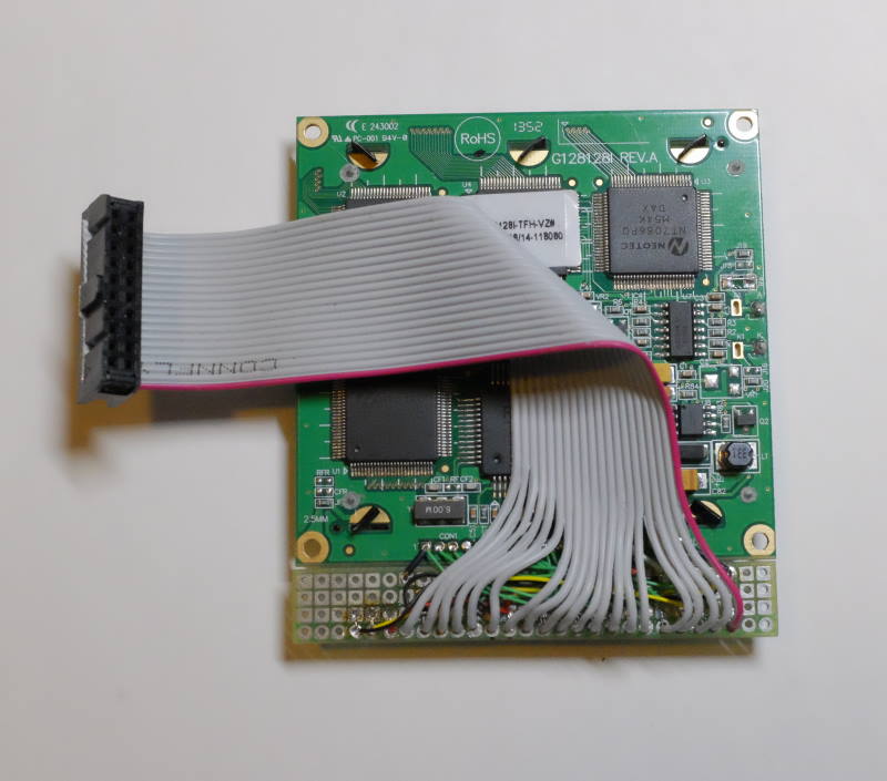
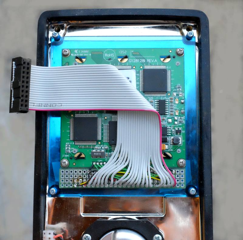
The following two pictures show the new LCD module mounted in this plastic bracket. Four 2-56 screws about 3/16" long have been used to attach the LCD module to the bracket. In the pictures, a new electrical interface card is visible. This will be covered in the next section.
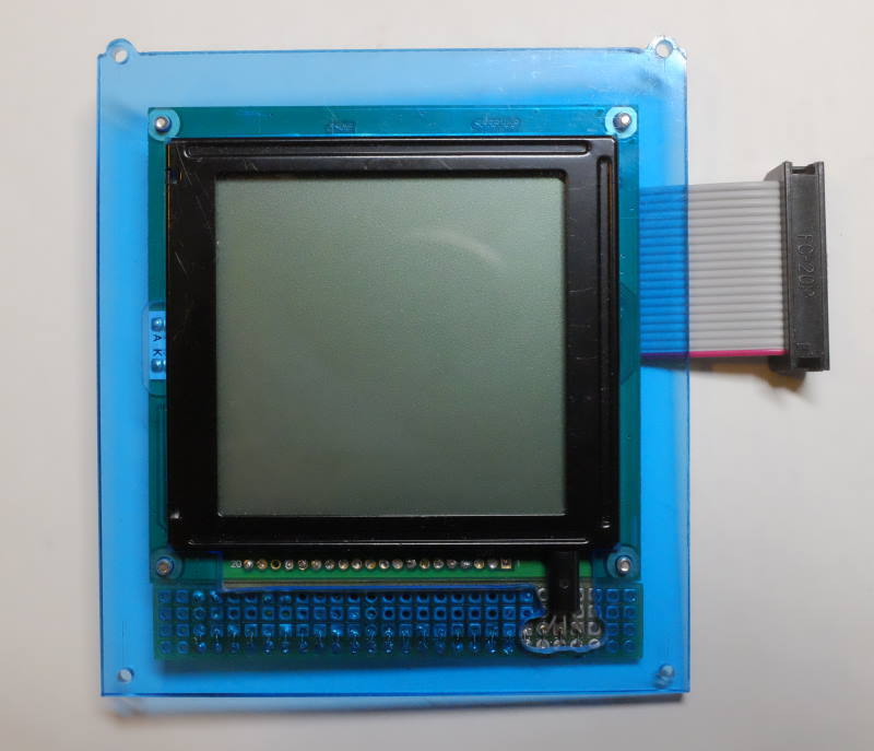
LCD mounted in bracket, front. |
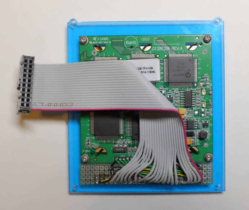
LCD mounted in bracket, back. |
Interface Board
The electrical interface adapter card that is attached to the original LCD is not useful for the new LCD module. The original had 22 connection pads with a 0.1" spacing. The new module has 20 pads with 2 mm spacing. All the same signals are there, but in a different order. The original had a Frame Ground pin that is not on the new one. The original also had a FS (font select) pin that was tied to ground. The new module doesn't have this as an external pin, but on the new module the same signal is already jumpered to ground on the circuit card.
Earlier, I posted a pdf file doc that gave tables describing the interface signals for the original LCD module and the 20 pins of signals from the main GR-135 module. For the new one, I have made a similar document.
To adapt the electrical interface, I made a small card from prototype circuit board with 0.1"-spaced through-hole pads. The board needs 3 resistors. I used 1206 sized SMD resistors soldered between adjacent pads on the proto board. Two are pull-ups to 5 V. The first is on the /RST signal; I used 10K. The second pulls up /RD; I used 56K. The third resistor is a dropping resistor that is in series to the backlight LED Anode. By experiment, I found that a 150 ohm resistor provided a usable light level with minimal current draw for battery life. If a brighter display is desired, this resistance could be lowered. The signal and power connections were hand soldered using 30 ga wire. A few short, heavier gauge wires were soldered between the LCD module and the proto board to give better mechanical stability.
The DS1821 temperature sensor is mounted on this circuit board too. The DS1821 is an obsolete part but I was able purchase a NOS part from a US vendor on eBay, so I used this part on my new board. If necessary, it shouldn't be too difficult to unsolder the 3 pins of the original sensor and move it to the new board.
For the connection to the GR-135 main module, I made a new flat cable with a new 2x10 (20-pin) socket connector on the end of the cable. Ultimately, I haven't used any of the parts from the original LCD module.
The following pictures show the construction of this new card and cable.
LCD interface board and cable. The temperature sensor is soldered to the 3 pins just to the left of the left-most flat cable wire. |

Wiring shown on the interface board. |
Front side of the interface adapter board. The DS1821 temperature sensor can be seen in the lower-right. |
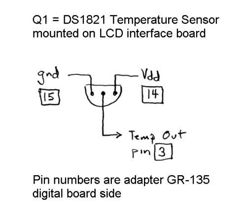
Temperature Sensor circuit. |
Arduino Testing
For the first level of testing of the new LCD module, I used the Arduino setup that I used to generate the test patterns on the old module at the beginning of this page. For the negative voltage required to generate the Vo contrast signal, I temporarily tapped into the negative Vee supply that is available on the new module, but not used for GR-135 operation. I had a pot connected between +5 V and Vee to allow for an adjustable Vo contrast voltage to the LCD. In the testing, I found that with good contrast setting, the Vo voltage was about -12 V. The following shows a test display from an Arduino program on the new module.
New LCD module, test pattern from Arduino. The green wire is temporarily tapping the negative Vee voltage from the module. |
GR-135 testing
Having shown that the new module works, I next wanted to test with the GR-135 but I didn't want to assemble all of it yet. To aid in that, I made a temporary test switch module so that I didn't have to connect the top cover to the main module just to have the handle's selector switch. The next pictures show this test switch device and the circuit for it.
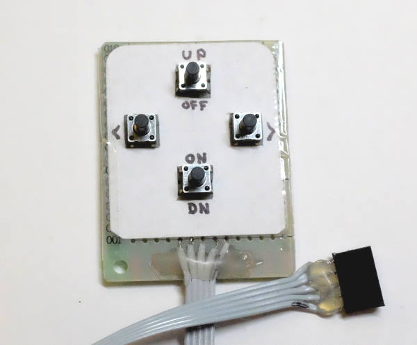
Selector switch for testing. |
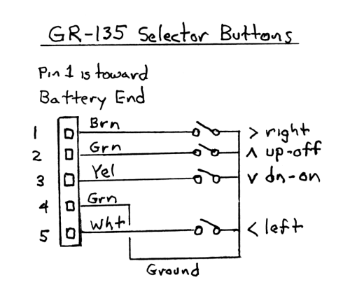
Switch circuit. |
With the testing switch attached, I connected the new LCD module cable to the GR-135 main unit. Batteries were installed and the unit powered up with the 'ON' button. Initially the display looked good as shown in the following picture, but after several seconds it became all black.
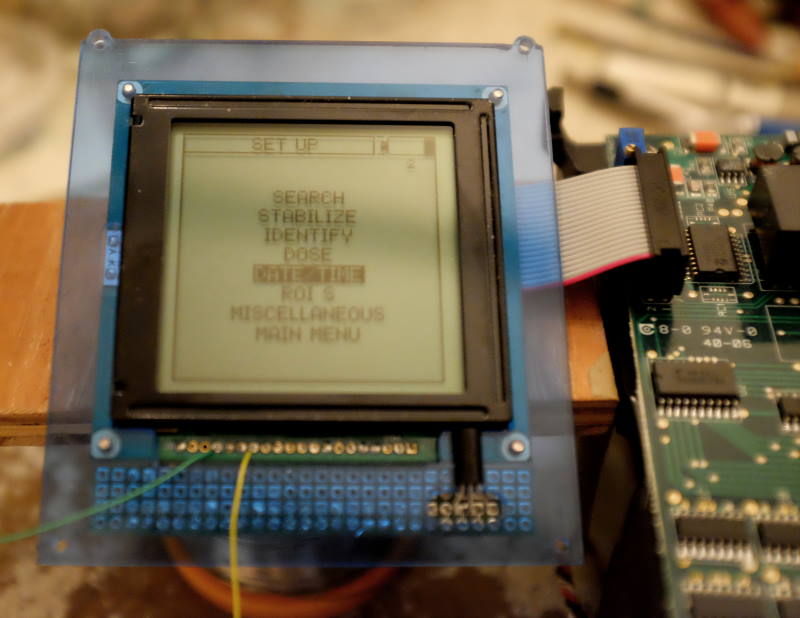
Testing on the main unit. The green wire is the Vee output from the LCD module. (It is not being used here.) The yellow wire is attached to the Vo contrast voltage input, so the voltage can be measured. |
Contrast
The contrast of the LCD is determined by the voltage that is applied to the Vo pin of the module. In the Arduino testing I determined that best contrast for the new LCD module was achieved with about -12 V on Vo. When I started testing on the GR-135 module, the display was good initially but in a minute or so it suddenly became completely black. (I didn't get a picture in that state.) After this shift to black, I checked the Vo voltage and found it was between -13 and -14 volts.
Initially, I was puzzled why the GR-135 design did not use the negative Vee provided on the LCD module. The GR-135 must be providing its own negative voltage to generate the negative Vo applied to the LCD module. To sort this out I traced out how the Vo was generated on the digital board of the GR-135 main unit. The following two diagrams show what I discovered about how the Vo to the LCD is generated.

LCD Vo voltage and center adjustment. |
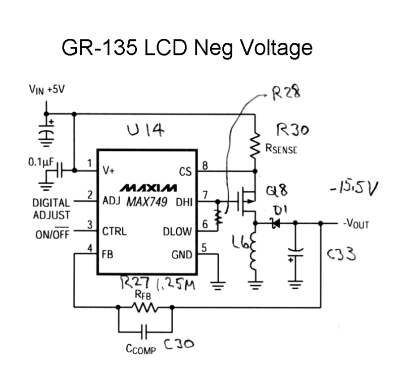
Digitally adjustable negative LCD supply for Vo. |
Tom had discovered with his GR-135, that if he heated or cooled the DS1821 temperature sensor next to the LCD that the LCD contrast could change radically. This implied that the Vo voltage must be changed depending on the sensed temperature. With the original LCD, before I tried the new one, I decided to try to trace out the circuits of how this worked.
The first circuit above shows how the Vo voltage leaves the digital board to the LCD. R24 and pot P1 form a divider between +5 V and the negative LCD supply on the digital board. The pot can be seen as a blue device in the earlier two pictures that show the mounting feet for the main GR-135 circuit module. It is right next to where the cable from the LCD plugs into the main unit. The Vo voltage comes from the wiper of this pot P1 so that Vo can be adjusted to set the nominal value. On the drawn circuit, the negative supply voltage is labeled 'GR-135 -15.5V typ'. The -15.5 volts is what I measured while working out the circuit.
I traced back further and found that the negative voltage was coming from a Maxim MAX749 chip. The datasheet calls this a 'Digitally Adjustable LCD Bias Supply'. The microprocessor on the board can send it a serial stream that sets the negative output voltage. The typical circuit from the 749 datasheet seemed to almost match the circuit on the GR-135 so I have copied it as the diagram above. I added the component labels from the GR-135 circuit and one extra resistor (R28) that I found.
If I understand the circuit correctly, the GR-135 micro should be able to digitally set the negative supply voltage between about -8.3 and -25 volts. This is beyond our control and defined by some algorithm in the microcode. I would expect the -15.5 V that I measured is a typical value. Assuming this supply is making -15.5 V, the pot P1 could be adjusted to put Vo between about -8.1 and -15.5 volts. From experiment we would expect about -12 V is the right value for the LCD which should be around the mid-point setting.
So in my initial testing, the sudden change of the contrast from OK to wiped-out black, was probably due to the microprocessor, for some reason, deciding to change the negative supply voltage. I checked the Vo voltage and found it around -13 V. I adjusted P1 to bring the display back, and indeed, the Vo was then near -12 V.
I put the GR-135 back together and used it over a few hours. I ran the CS137 calibration and a couple scans. All seemed well and the display was fine. Eventually I remembered that on the GR-135 you can use the left and right buttons to adjust screen contrast. Check the manual for details. When I tried that the screen shifted to washed out, nearly unreadable, and I couldn't get it back with the left/right buttons. I can't explain that, but I opened the GR-135 again and adjusted P1 to a point where I could move the contrast through a reasonable range with the left/right buttons.
So, advice for anyone who replaces the LCD module. Use P1 to set the contrast level, but while the GR-135 is still open, try adjusting the contrast with the left/right buttons and if necessary, readjust P1 for a sensible left/right range before putting the GR-135 back together.
End of the Process
I haven't yet shown how the new display mounts into the top cover, so here is a picture of that.
New LCD module mounted in GR-135 cover. |
And, now, the most important. Here are a few pictures of the new smaller LCD display operating in the Gr-135. Some are with the backlight off and some with it on. Other than being smaller, I think this is a very usable option.
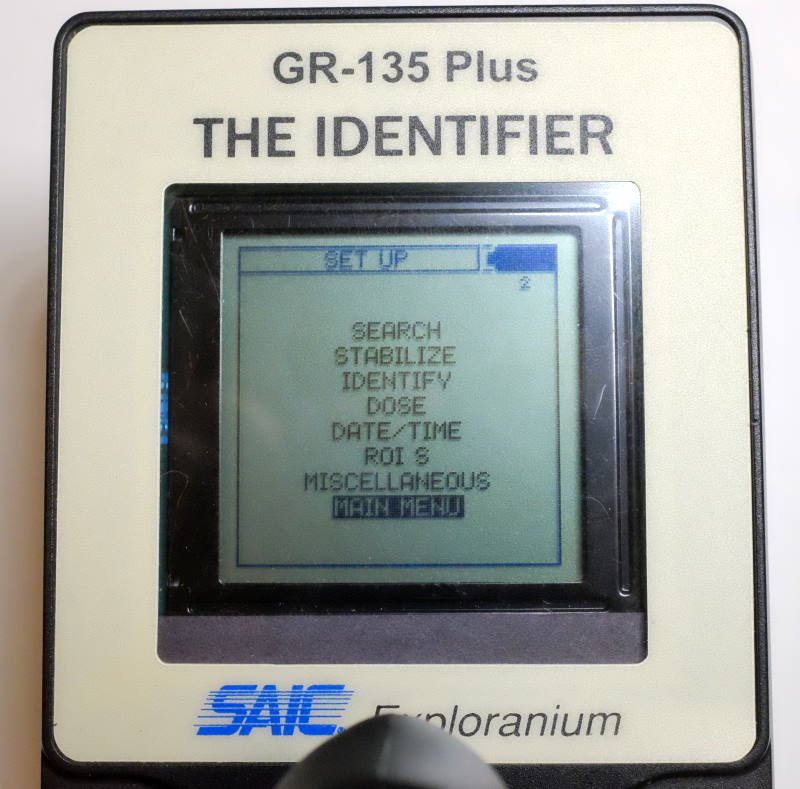
Menu, backlight off. |
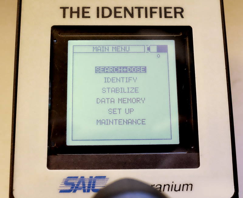
Menu, backlight on. |
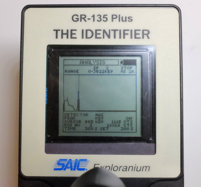
Spectrum, backlight off. |
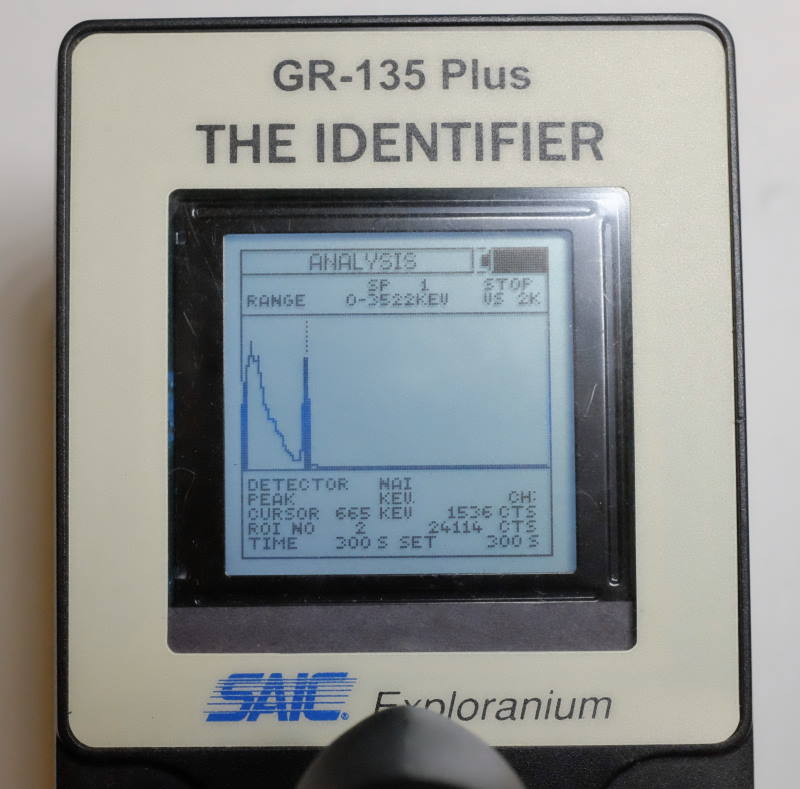
Spectrum, backlight on. |
Some of these pictures appear to have a blue tint on parts of the displayed graphics or text. I think this is an artifact of my camera or color balance. All I have seen on the actual display is black over light gray (no backlight) or over white (backlight on).
Conclusions
It's too bad that SAIC chose an LCD module that apparently had a limited life failure mode, but maybe that is why so many have been offered recently for not horrible prices for amateur users. It's also unfortunate that it is so hard, now, to find a replacement LCD that is form and function equivalent to the original. Tom found one, but it is unclear at this point if more will be available at a reasonable price.
As described on this page, I found a Crystalfontz CFAG128128I-TFH-VZ graphic LCD module that can be adapted to work in this application. This one has a good display but it is about 3/4 the size window of the original. This does make it harder to read the small text elements (especially for those of us with aging eyes) but I think it is acceptable. It is certainly better than an original LCD with 20-30% of its pixel columns dead.
The Crystalfontz LCD's are easy to order from their web page in quantity one. There are slight price breaks for larger orders. You must then pay shipping, but they have more than one option and the shipping costs seem fair. Delivery for my order with cheapest shipping option was pretty fast. At the beginning, I contacted their support hoping they might be able to provide a more perfect replacement like the original. That didn't work out but I got an intelligent reply from them very quickly and it seemed the person checked overseas to see if there was anything closer.
Making the bracket was a lot of work with pretty good accuracy required. I don't know how that could be made easier without a lot of cost to have them made. The way I made the interface card was also a lot of tedious work. If there was enough demand, it shouldn't be to hard to lay out a circuit board and have some made. That would require time and some extra money.
On this page I have tried to provide all the details needed for someone to duplicate my solution. Making the bracket requires some pretty good tools and mechanical skills if done as I did it. Making the electrical interface the way I did needs decent soldering skills, plus some time and patience. But as shown here, it can be done.
One final thing I noticed. Once the GR-135 is opened up, it is really hard to get the battery case properly aligned in its window in the outer case as the unit is reassembled. I suspect this is why so many of these GR-135's have been offered for sale with missing battery doors. I have not seen a GR-135 with its original door, but I think if the battery box is not properly aligned it would be impossible to get the door to fit the way it should. My door is long gone, but I made some minor changes to make the battery box line up easier. I may try to describe this on another web page.