Soldering in a Toaster Oven -- KK6MK's methods
This is a description of a method I used to solder surface mount boards in an adapted toaster oven. Most of this is based on earlier methods used by others. There are links provided to those other sources. This page is adapted from a paper I wrote for MUD 2012.
I started reading about homebrewing boards a couple years ago but only just recently had a good reason to begin doing it. As with most things, I have begun with a solution that is slightly more engineered than necessary, but this crowd should relate. Although I am very new to this, the results have been good so far, so I thought I would share the methods that I have used.
Learning from others
I found a link to web pages at Sparkfun about reflow that I will repeat here [1]. I found those pages a while ago and it remains one of the best resources. Seeing pictures and descriptions of their process was very informative and helped me overcome my fear of the solder stenciling process to lay down solder paste on the pads of a small-feature board.
Other people I know have reflow-soldered some of their own boards by merely putting them in a toaster oven, cranking it on high, and watching to see the solder melt, then turning it off. I’m sure that works fine, but I wanted to try a more tightly controlled heating process. I had gotten interested in temperature measurement and process control for some other interests. Adapting what I had to a toaster oven seemed easy. I implemented this on an old toaster oven (more details later) and it seemed to work but I didn’t have a project with a blank board to give it a real try. My first experiments were to heat surplus boards then take them out with pliers and whack them on a table to remove parts without severely overheating things.
Early this year at a meeting of the 50 MHz and Up Group I learned that Lars AA6IW had designed and built a few copies of a board that I was interested in. (Described in another MUD 2012 paper, “A 3600 MHz Synthesizer / Mixer Board”.) He wanted to give his design over to the ham community but wanted someone else to take over the project. I volunteered.
This led to a series of things I had not done before – finding a vendor and getting boards made, researching prices and ordering parts, and eventually assembling a few boards myself for verification, testing and measurement. This last part got me to bring out my toaster oven project again.
The Synth/Mix project has a number of parts that are small so they would be a bit difficult to hand solder, but it also has one part, the PLL chip, that can’t be hand soldered with a soldering iron. The chip, pictured at right, has relatively big pad in the center underneath, so reflow is the only practical way to mount it. |
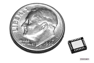
|
Temperature controllers
|
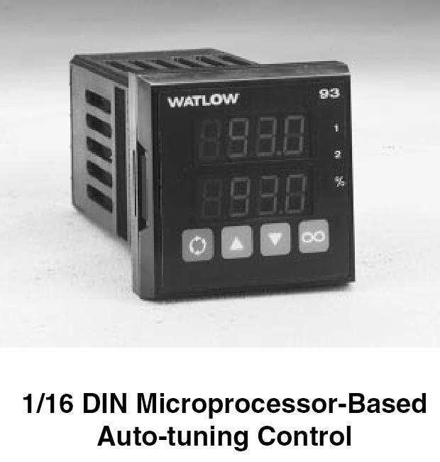
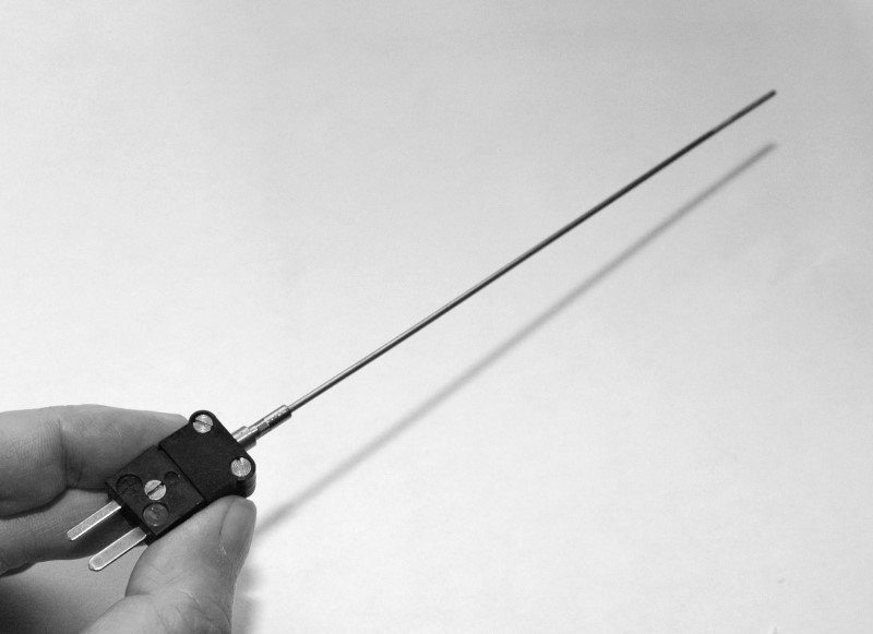
During my investigation of temperature measurement and control a few years back, I became aware of temperature controllers that are made by several manufacturers. One common size is 1/16 DIN controllers, which have a face about 2 inches square and are about 4 inches deep behind the panel. This seemed like a nice small size. To the right is a picture of a controller by one of the major manufacturers. Most of these can use several kinds of sensors for measuring temperature, but one of the most common is a thermocouple. This is a relatively inexpensive and rugged choice for our oven. Most thermocouples are just lengths of wire welded together on the sensing end and they may or may not have a plug on the instrument end. Years ago in a surplus store browse, I obtained a few thermocouples that were package in a thin steel tube about six inches long, ending in a plug. These seemed ideal for sticking into my toaster oven. Picture below… |
|
These temperature controllers can have many options, such as the types of sensors they can use. Another is how the output is controlled. Many will have relays inside. Some can generate a low voltage DC on/off output. I like this version as it can be used to switch a solid-state relay like the one shown to the right. The SS relay pictured is like the one I used in my toaster oven controller. This one is capable of controlling up to 240 VAC and can switch a load of 18 Amps. A good fit for the toaster oven. |
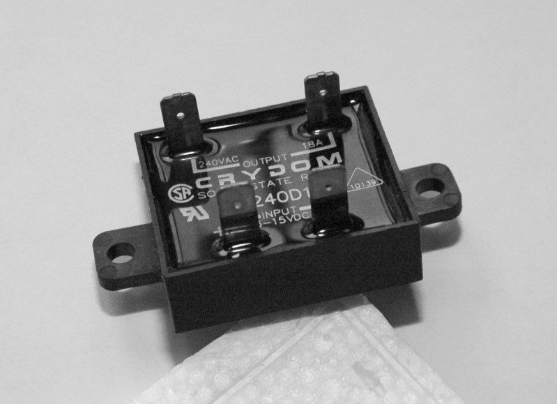
|
These controllers usually contain a microprocessor that implements PID control of the temperature. The sensor input allows the controller to accurately control the heating (and sometimes optionally cooling.) Most have an auto-tuning mode where the controller learns the system response and sets appropriate parameters for a PID loop. All of these controllers should be able to efficiently take the oven to a set temperature and accurately keep it there within a few degrees.
The controller I used for my oven has an additional feature that not all of them have which is the best part for this application – that is the ability to program a temperature profile with a series of temperature ramps and soaks with a time defined for each stage of the profile.
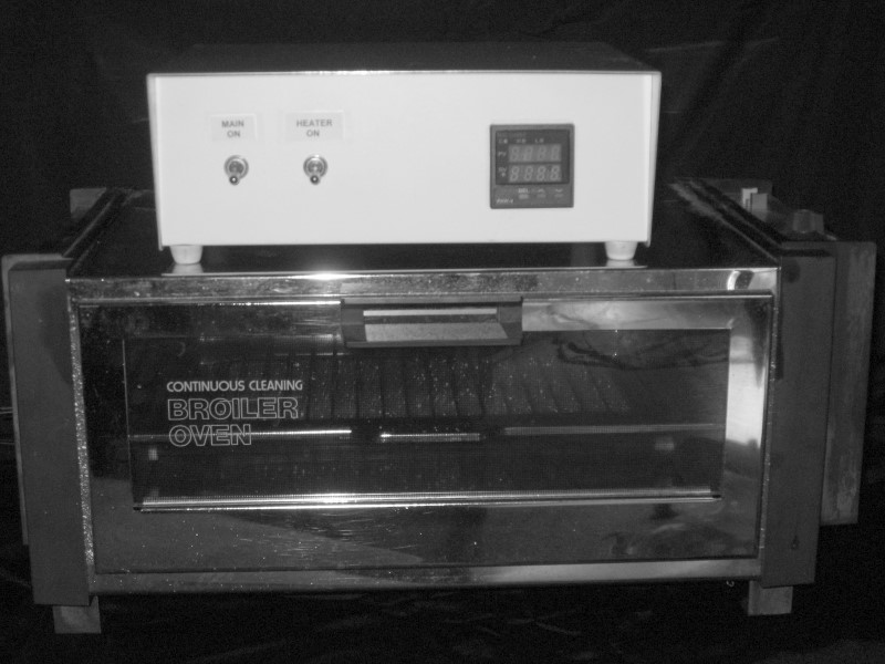
The oven
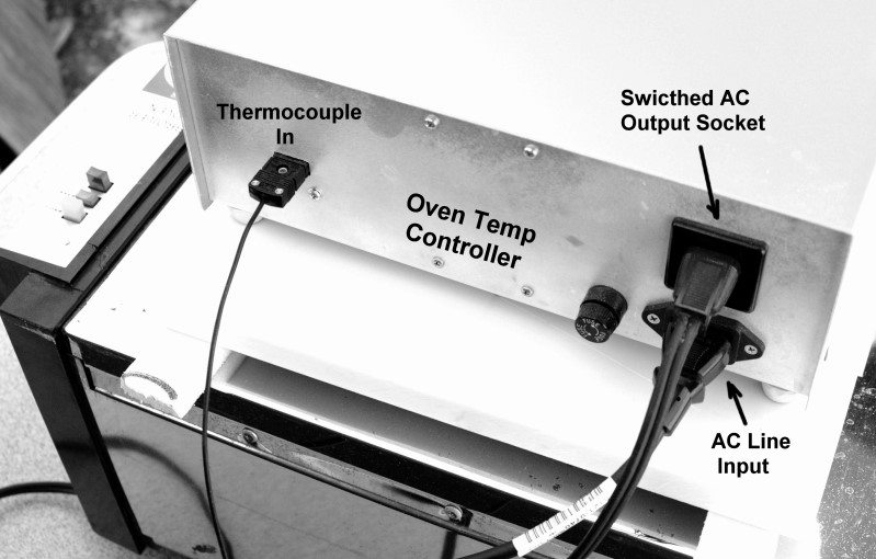
In my garage, I had a very old oven (possibly from the 70’s) but it had very little use, so was in good shape. The oven is pictured below with my homebrew temperature controller on top. The picture on the right shows the connections on the back side of my controller.
|
|
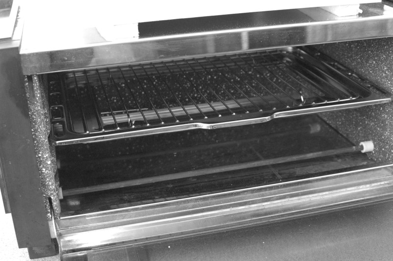
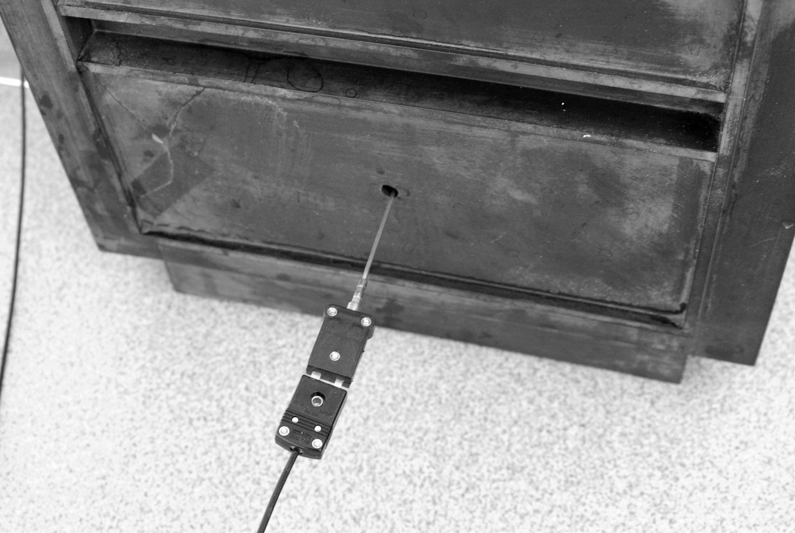
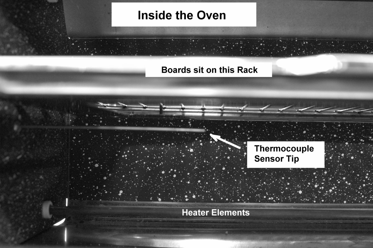
On the right, the door is opened looking into the oven. Beneath the wire rack is a sheet metal drip pan. This pan supports the wire rack so it must remain. I cut the center out of this pan to allow the heat to flow better, by convection, through the oven. I drilled a hole in the left side of the oven for inserting the thermocouple. The pictures below show the thermocouple location. |
|
|
|
Temperature profile
The graph below shows the recommended temperature profile for reflow soldering of the PLL chip, from a TI datasheet.
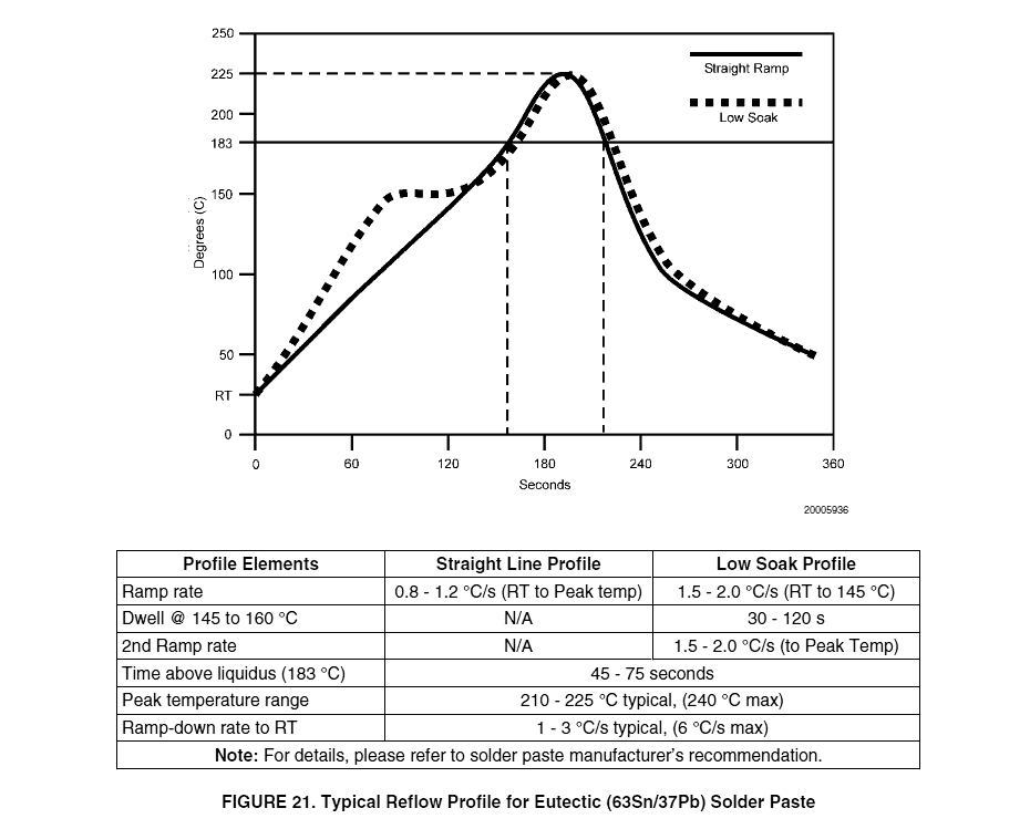
The horizontal line at 183 C on the recommended graph is the melting point for 63/37 solder.
My toaster can’t heat fast enough to achieve the recommended temperature ramp. The graph below shows the best compromise that I programmed into the temperature controller.
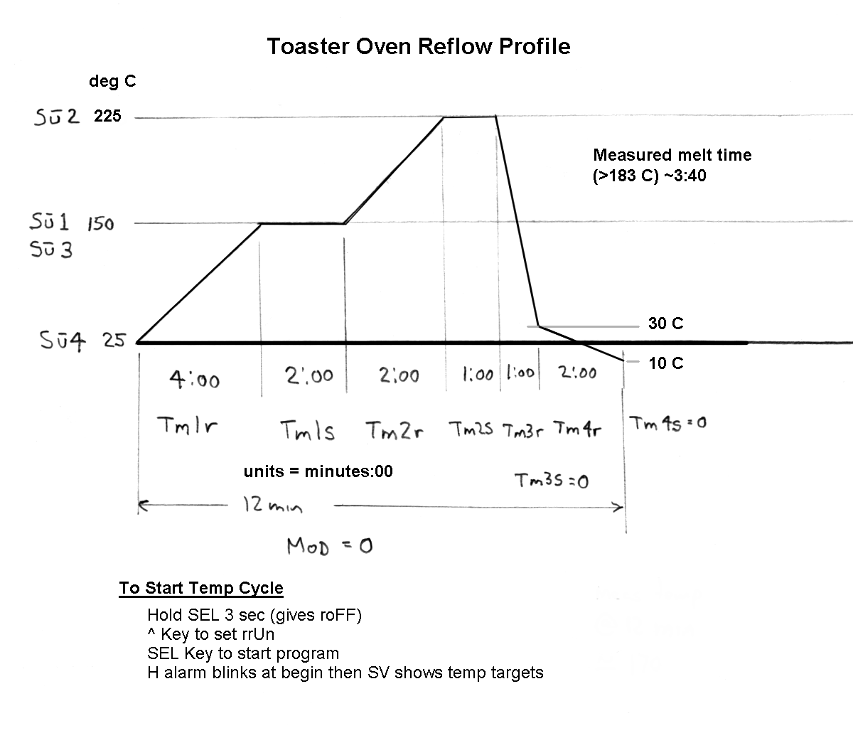
So far, this program seems to work well. The boards probably stay above 183 C a little longer than they should but the minimum timing resolution on my temperature controller is 1 minute, so it would be hard to improve this profile much.
If I am near the oven when the profile starts to drop from peak temperature, I open the door to let the oven and board cool a little faster. Probably not necessary, but it shortens the cool down a little and makes me feel better.
I was a little concerned that the convection heating might not heat larger components fast enough but so far everything I have tried has soldered well. I have only made a few boards since I started this but they have all worked and I haven’t seen any problems with the difficult PLL chip.
Preparing boards to solder
The Sparkfun tutorial pages [1] have a great description on the process of hand stenciling the solder onto the boards, so I won’t go into every detail but I’ll describe some of my overkill methods that differ from the Sparkfun descriptions.
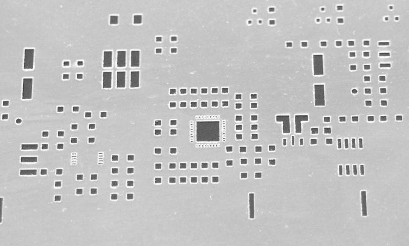
I ordered my stencil from Pololu [2]. This vendor was mentioned on the Sparkfun pages. The stencil I got was 3-mil Mylar. I ordered the thinner 3-mil material because of the detail on some of the smaller parts, particularly the PLL chip. Below is a close-up of the apertures in the stencil I got.
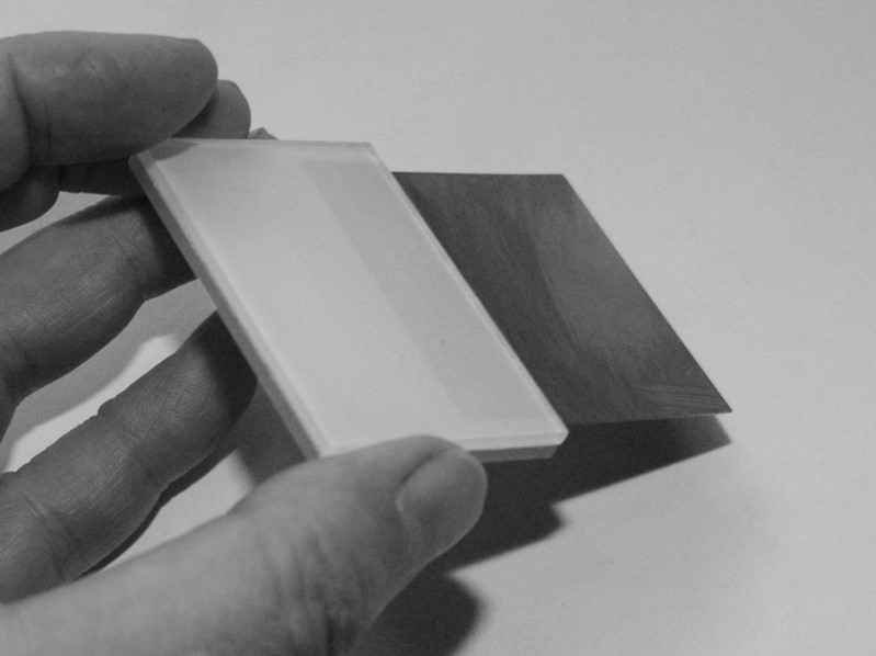
The solder paste gets spread using a thin flexible metal spatula. I learned this from Sparkfun and other pages. I didn’t know where to get such a thing, but on a notion, I went to a local art supply store. There I found a thin metal rectangle sold as a tool for scraping clay sculptures. It looked good to me. When I got it home I cut it in half to make two squeegees. I made a handle for it by clamping the edge of the blade between two pieces of plastic held together by double-stick tape. I made sure the business end of the blade was smooth and straight by honing it on a diamond stone such as you would use to sharpen a knife or chisel. On the right is a picture of one of the two resulting tools. |
|
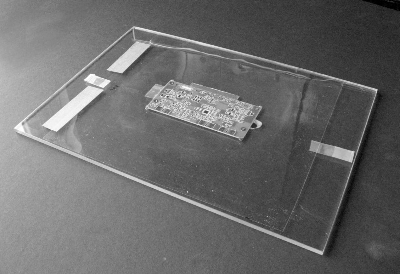
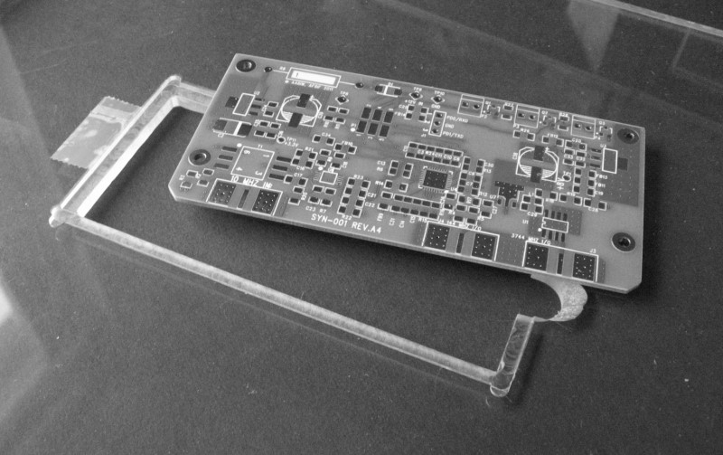
I ordered 50 PCBs for the project and wasn’t sure how many I would build up myself this way. I decide to play it safe and make a fixture to hold the board aligned for stenciling. I have a milling machine, so I used it to mill a pocket in a sheet of acrylic just big enough to hold one of the boards. The pocket has a lip to hold the bottom of the board and the depth of this lip holds the surface of the board just a few thousandths of an inch above the surface of the acrylic sheet. On one end of the pocket I cut a U-shaped aperture so a finger can easily lift the board out of the pocket. See pictures below.
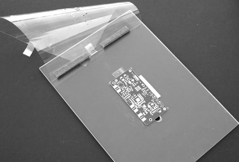
The Mylar stencil is taped to the acrylic with two pieces of painter’s tape on one end of the Mylar. Before sticking this tape down, I put a board in the pocket and aligned the stencil to the pads, then pressed the tape down to hold the alignment. These tape strips also act as a hinge to open the stencil for inserting or removing a board. One picture shows the Mylar closed and one shows it open. A small piece of Scotch tape helps hold the other end of the stencil in place for the stenciling process.
|
|
The solder paste I have been using is a syringe of Kester EP256 63/37. I got it by ordering from CML Supply [3]. The solder has a shelf life and I store it in a jar in the refrigerator between uses. (If anyone was wondering, I live alone.)
I use it by squeezing out a couple thick lines of paste onto the stencil just above the apertures at the end of the board. Then I drag the solder over the board with the metal squeegee. In my early state of learning, I seem to have problems getting even coverage across all of the board in one swipe, but I find that the process is pretty forgiving and squeezing out a little more solder above a spot I missed and dragging again over that seems to work OK.
Since I ordered the thinner 3-mil stencil material, I was a little worried that there might not be enough solder paste on the pads for larger parts like a surface mount header connector. Looking at the joint after reflow soldering, they all look good to me with a visible meniscus of solder between the part and pad.
I have been cleaning up the stencil and tools by first wiping off the heavier residue with a plain paper towel, then finishing up with paper towels and a little drugstore isopropyl alcohol.
Placing parts
Quite a while ago I purchased a used zoom binocular microscope. In its normal configuration it is about 5 to 20 power. That was a great purchase and every year my aging eyes make it more useful for even day-to-day tasks.
So I do the parts placement with fine tweezers under the microscope. In addition to seeing more exactly, the visual gain seems to help the body’s feedback loop to dampen any shaking a little. As others have mentioned, being in a rested state and a lack of caffeine helps the process. Regardless, placing more than a few parts is tedious, but that is the nature of the game.
Before I begin to stencil the board I organize the parts needed for the number of boards I plan to assemble. From a Kuhne kit I built several years back, I saved a container that held the parts for the kit. It has 32 little bins. Here is a picture…
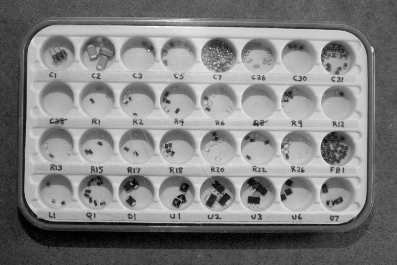
I place the parts I need for these boards in the bins. The labels written for the bins are on narrow strips of tape so I can set it up for a different project later. The label for each bin is the lowest designator for that part number. For instance the bin for C7 holds a capacitor value that is used 19 times on this board as C7 … C25. There is only one C2 per board but I was planning to assemble three boards when this picture was taken, so there are 3 caps in that bin. (Some part designators have been crossed out due to changes and C1 was deleted, hence the header in that bin.)
To help keep the parts-placing process under control I use a laptop near by to help keep me on-task in this mindless process. I created an image of the board from the design files. I made a copy of this file for each part number, and using an image-editing program, I edited the image to show where on the board this part number needs to be placed. As an example, here is the image for C7 on the Synth/Mixer board…
In the actual file I used, the bars indicating where the parts are to be placed are in a bright color so they are much easier to spot while viewing on the laptop. Having created an image file for each of these parts, I put them all in a directory. Using the free viewer IrfanView, I open the first file on the laptop, place those parts, then the space bar moves me to the next image and the next part. If I thought I needed to install some of the parts in a particular order, I could rename the image files so they begin with 01 through up to 99. The viewer will open them in alphanumeric order so you can control the order they will appear when stepping with the space bar or arrow keys.
I have read (and seen in my own experience) that if parts get placed a little bit off, then when the solder melts, the capillary action of the solder on the pads tends to pull the parts into alignment. Still, I try to place the parts as accurately as possible. Similarly, if the paste is a bit sloppy in places, the solder mask and reflow heating tends to break any bridges. If I see messy spots, I do try to clean things up a bit with a toothpick or an x-acto blade.
Into the oven
I’m sure I could just sit the boards on the rack in the oven and run them through the reflow temperature profile cycle, but I envisioned that a finger fumble as I placed the boards on the rack could destroy my careful placement work. (Especially if the oven was hot from preheating or a previous reflow.) On my oven, the rack did not slide in and out smoothly either, so I wanted to avoid needing to do that. I decided to make a holder for three boards where I could slide the boards in and out easier and with a pair of pliers if necessary. Each of the boards I was doing has 4 mounting holes that are smaller than a 4-40 screw. I took a piece of aluminum sheet scrap and carefully drilled holes for 4-40 screws on the spacing for three boards. Here is the result …
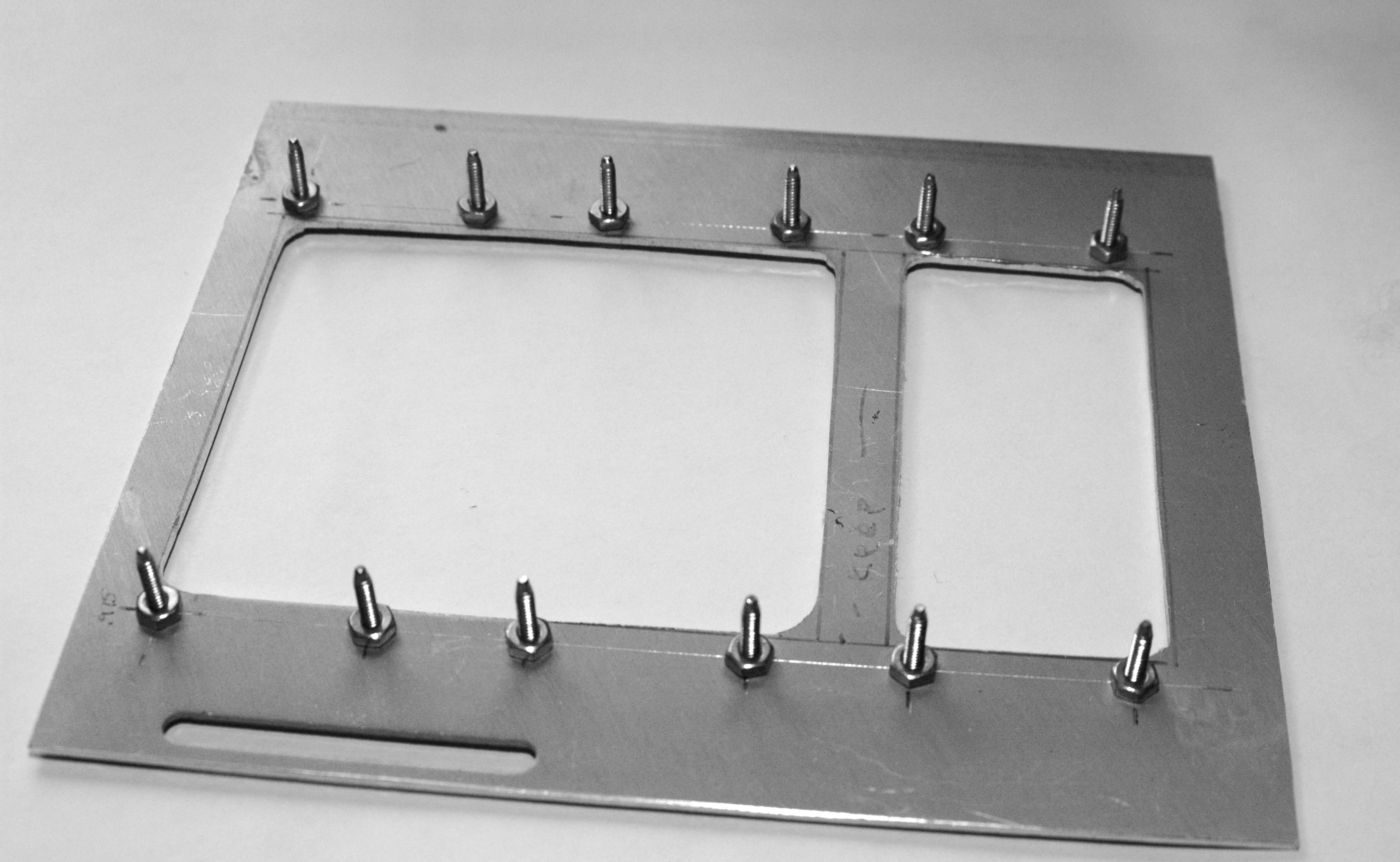
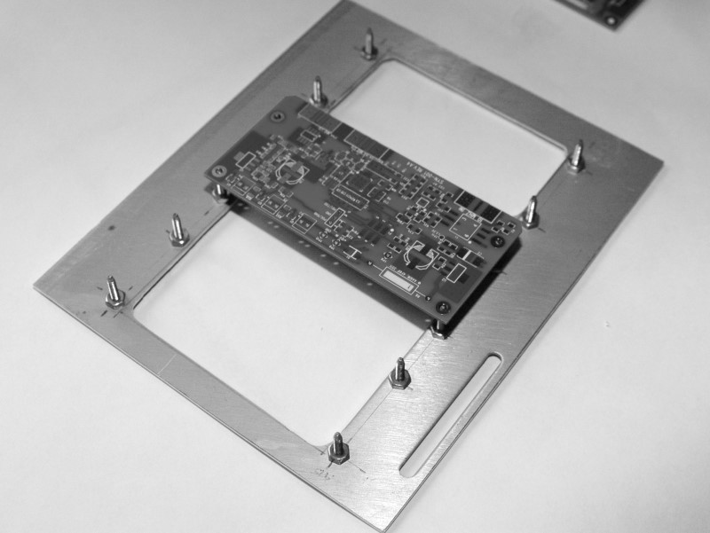
The ends of the screws have been cut down in diameter and tapered to fit in the board holes but keep the boards located at the tips of the screws. Here are pictures of the holder with just one and then three boards…
|
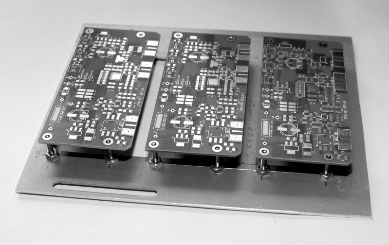
|
The center of the aluminum holder was cut out to allow for good radiant and convection heating of the boards. With only four small spots supporting each board the holder should not have much affect on the heating or cooling of the boards. The oven rack has its bars running from front to back, so sliding this holder onto the rack is easy. I have done reflow on both one board and three boards at a time. I haven’t noticed any difference in my process. My oven is fairly large, so if I was more production oriented, with a larger holder I think I could do six or nine boards in a batch.
Results
Here is a picture of one of the boards I made with this process…
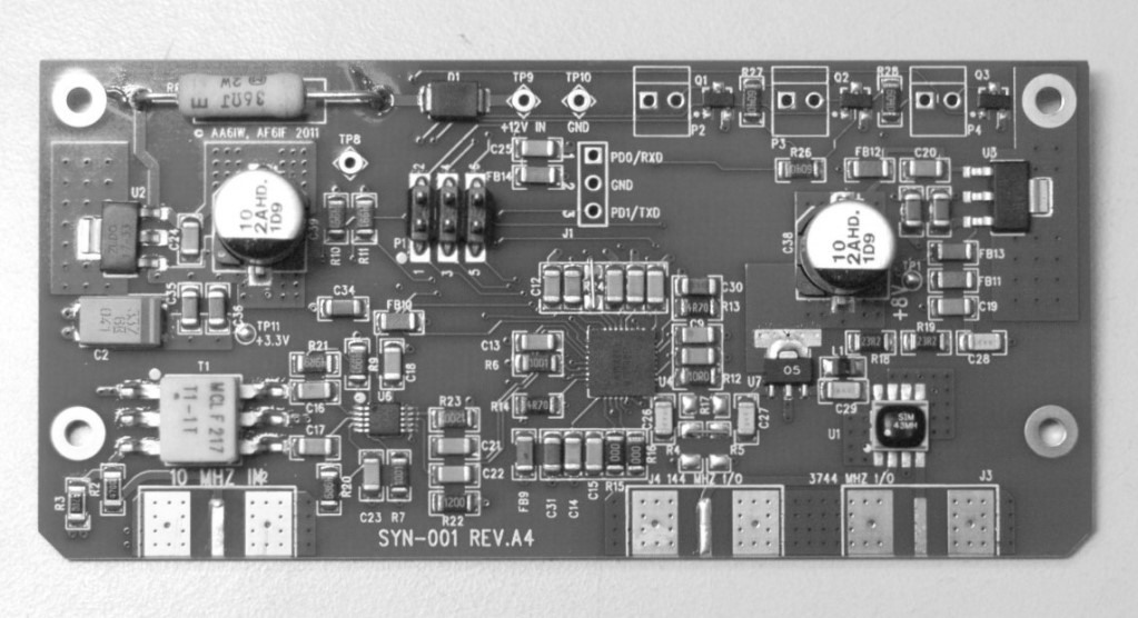
There are a couple spots where a component was changed to zero ohms and I made this change with a short piece of wire rather than a 0-ohm chip. These were also soldered during the reflow process, not after. The most challenging part is the PLL chip near the center. This part is a little less than .25 inch square and has nine pads under each edge. Additionally, the center under the chip is mostly a ground/heat pad. My sample size is a little small, so far, but I haven’t had a bad board yet with this over-kill toaster oven reflow process.
References
[1] Sparkfun turtorial, http://www.sparkfun.com/tutorials/58
[2] Pololu stencils, http://www.pololu.com/catalog/product/446
[3] CML Supply - solder, accessories, tools http://www.CMLSupply.com
[4] KK6MK’s project page for this board, http://www.xertech.net/Projects/Synth_proj.html
A PDF copy of the paper
You can download a copy of the paper on this subject that was done for MUD 2012.
*** The file is big, though, almost 9 MB! ***
- The PDF can be obtained with this link:
- YATORM.pdf