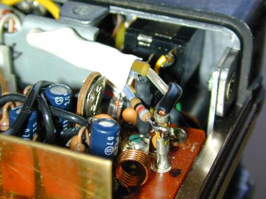
TX Pad modifications for TX power reduction.
The picture above, shows the completed pad installed on the TX board.
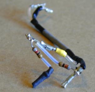
Above shows the detail of how the pad is constructed. One goal was to allow the radio to be converted back, so if the one resistor is unsoldered from the connector in the lower right, the attenuator can be removed. The other connector (with yellow shrink insulation) is just slipped onto a thick wire at the junction of the two resistors and can be unplugged. The black connector in the lower center is similar to the connectors on the coax and allows the attenuator to be plugged onto the DO pin on theTX board. This pin provides the RF signal coming from Q8 on theTX board. It is the signal we are attenuating with this pad.
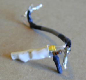
The picture above, shows the completed attenuator and coax. It is ready to be slipped onto the DO and E pins on the TX board. The far end of the coax goes to the IN and E pins on the Final board.